Drawing Dies Materials and Types of Wire drawing According To Dies
🔗Stages of Wire drawing process
🔗Wire Drawing Applications and Advantages
Types of Wire Drawing Die Material
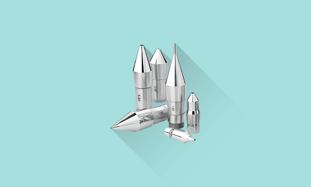
Dies are the critical components of the wire drawing process. Dies are used to shape the wire as it is being pulled through the machine. They are typically made of tungsten carbide, ruby diamond, or other hard materials, and their size and shape must be carefully controlled to ensure a consistent product. Diamond dies are known for their exceptional durability and hardness. When it comes to creating thin wire, diamond dies are often the go-to tool for manufacturers. Mandrels used for tube drawing are typically crafted from similar materials as the dies.The dies are arranged in a series of steps, with each step reducing the diameter of the wire by a predetermined amount, the reduction in cross-sectional area usually being about 30 per cent. A steel casing houses the dies, which serves as a backing and enables effortless die replacements.
The modern alloy-steel dies have been a reliable choice for manufacturers for many years thanks to their exceptional durability and lifespan. However, the emergence of tungsten-carbide dies has revolutionized the industry. The growing demand for maximum efficiency has led to the increasing replacement of steel dies with tungsten-carbide ones.
Ruby or diamond dies are also used as drawing die, but their usage is usually limited to drawing fine wires less than 3mm in diameter. These jewels are first trimmed and then drilled. Small drills fed with diamond powder oscillate for several hours to pierce holes in these jewels. Each pierced hole is finished and polished to within 0.00025 mm. These jewels with finished holes are then mounted in metal holders.
Sections of Wire Drawing Die with Diagram
The die is designed with several distinct sections to ensure a smooth and efficient forming process.
Bell radius and and Entering angle: The initial section of the die features a bell-curved opening that does not directly interact with the workpiece. Instead, this area funnel lubricant into the die and facilitates the entry of the wire rod without damage from the die edges.
Approach angle: Following this is the approach section, where the actual forming of the workpiece takes place. The approach section's cross-sectional area gradually decreases as it nears the bearing surface. The approach angle usually is ranging 5 to 20°. This angle depends upon the work material. Generally, harder material requires a smaller reduction angle, and softer material requires a large angle.
Bearing surface: The bearing surface is where the workpiece is ultimately shaped. The bearing surface, sometimes referred to as the land, is responsible for holding the precise geometric cross section for the length of the draw. This section serves as a sizing operation, ensuring the workpiece adheres to tight tolerances. The length of the bearing surface is normally expressed in percentage of borehole diameter. Generally, the bearing surface length for harder work material is longer than the softer material.
Back relief angle: At the end of the draw is the exit zone, which features a steeply angled section similar to the entry zone. This angle is normally 30°. This section is designed to protect the drawn work from the edges of the die. Back relief angle help drawn wire exit smoothly from bearing surface.
Types of Wire Drawing According to Dies
There are several different types of wire drawing processes, each with its own specific requirements and advantages:
Single Block Drawing
In single block drawing, the wire is pulled through a single die using a capstan or motor. This process is suitable for small-scale operations or when only a small reduction in diameter is required.
Multi-stage or Continuous or Tandem Drawing
This technique involves pulling the metal rod or wire through multiple dies, each reducing the wire's diameter until the desired diameter is achieved. It is normally used to produce fine wire. Manufacturers rely on tandem machines to draw small-diameter wire, which features a series of water-cooled die blocks. This cooling system helps to dissipate the heat generated during the drawing process, ensuring that the dies remain at a consistent temperature and minimizing the risk of damage to the wire.
Tandem drawing involves passing the wire through a series of dies mounted on separate, rotating capstans. Each capstan pulls the wire through a die, reducing its diameter before sending it to the next capstan. This process allows for high-speed, automated processes, higher production rates and larger reductions in diameter.
High deformation with less surface temperature can be achieved through tandem drawing. As the wire progresses, during the period the wire is between dies, the temperature gradients between the wire surface and the interior are reduced. Additional cooling can also be used. If extensive deformation is required, intermediate anneals must be performed between the various stages of drawing. This process is ideal for large-scale production and consistent product quality.
How Fine Wire Drawing Is Done?
For manufacturing fine wires, a composite wire rod undergoes the drawing. For example, a platinum wire 0.00003 inches thick, finer than a human hair, has been drawn by a composite wire rod. First, encasing the platinum wire in silver. Thus increasing the overall diameter for feasible drawing. After drawing, it is treated with nitric acid. Nitric acid dissolved the silver, leaving a platinum strand which was visible only under a microscope.


