Construction And Working Principle of Autocollimator with Drawing
🔗Autocollimator - Applications advantages and limitations
An autocollimator is an optical instrument that is used to measure small angular displacements or deviations in the alignment of optical surfaces or mechanical parts with a high degree of resolution. It works by projecting a collimated light beam onto a surface and then measuring the angle of reflection back to the instrument. The principle of operation is based on the fact that the angle of incidence of the light beam is equal to the angle of reflection. So any deviation in the alignment of the surface will be reflected in the angle of the reflected beam. Autocollimators are typically used in precision alignment and measurement applications.
Components of autocollimator
An autocollimator typically consists of the following parts:
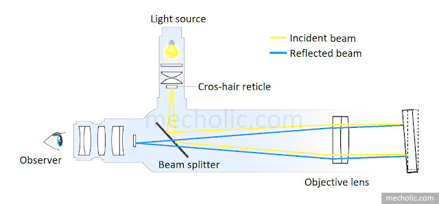
Light source: This component generates the collimated beam of light. It can be a laser or a light-emitting diode (LED).
Telescope or objective lens: This is the main component of the autocollimator and is used to project a collimated beam of light onto the mirror or retroreflector.
Mirror or Retroreflector: This component is the target of the collimated beam of light and reflects the beam back into the telescope.
Beam Splitter: It separates the outgoing and reflected light beams. Help to direct the reflected beam to the eyepiece or sensor.
Sensor: This component measures the angle between the incident and reflected beams. This can be a reticle, a digital readout, or a specialized sensor such as a quadrant detector.
Mounting mechanism: This component is used to mount the autocollimator onto a stable platform, such as a tripod or a table.
Some autocollimators may have different variations or additional components depending on the specific design and application.
Working principle of autocollimators with diagram
The autocollimator telescope or objective lens is used to beam a collimated light onto a reflector, which is deflected about the vertical plane. The reflected light is then magnified and focused on an eyepiece or photodetector. The deviation between the projected beam and the reflected beam is used to determine the angular tilt of the reflector.
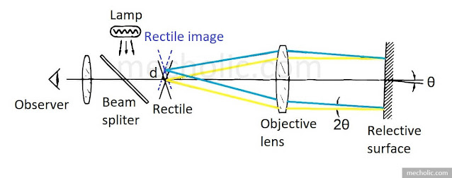
The figure above illustrates the working principle of an autocollimator. The reticle in an autocollimator is an illuminated target with a cross-hair pattern placed in the focal plane of the objective lens. A plane mirror perpendicular to the optical axis reflects the image back to the observation point. A viewing system, typically an eyepiece, is used to observe the relative position of the cross-wires. If the plane reflector is tilted by a small angle θ then the reflected beam will deflect by angle of 2θ. Results in the displacement of the reticle image by an amount d. Regardless of the distance of the reflector, the displacement of reticle image d=2fθ
Here, f is the focal length of the objective lens.
From the above equation, it is clear that the sensitivity of an autocollimator is directly related to the focal length of the objective lens. Longer focal lengths result in greater linear displacement for a given tilt of the reflector but also decrease the maximum tilt that can be measured. Thus, there is a trade-off between sensitivity and measuring range.
Autocollimators are sensitive to air currents between the optical path and the target mirror, which can cause fluctuations in measurement results. To avoid this, autocollimators are housed inside sheet metal or plastic casings to ensure that air currents do not affect measurement accuracy. To combat this, autocollimators are housed in sheet-metal or PVC plastic casings to protect against air currents and maintain measurement accuracy. [Why is the autocollimator housed inside an air-tight casing?]


