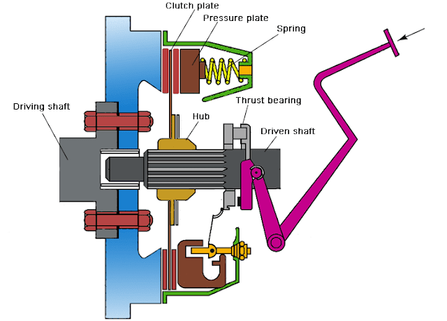
Design of Plate Clutch (Uniform pressure theory and uniform wear theory)
The amount of torque transmitted depend on axial force, the coefficient of friction, the area of contact.
🔗Energy Loss by Friction Clutch During Engagement
🔗Difference between Single plate clutch and Multi plate clutch
Design of single plate clutch
T = Torque transmittedµ = Coefficient of friction
r1, r2 = External and internal radius of contact surface.
p = Intensity of pressure
W = Total axial load
There are two cases, uniform pressure and uniform wear.
1. Uniform pressure theory
Assuming the pressure is uniformly distributed over the entire surface of friction face. i.e. p = constant
![]()
![]()
Mean radius of friction surface,
![R=2/3 [((〖r_1〗^3- 〖r_2〗^3 ))/((〖r_1〗^2- 〖r_2〗^2 ) )]](https://blogger.googleusercontent.com/img/b/R29vZ2xl/AVvXsEjb51sDBuSPGOhW_6ENGluB1mihUIDKGvk6i6iUGYwk8bfhgzzchwe6FysUFKha9hlWcsyZwpktq-tQuUT_nb8-zJEn6ywl6eumW_1oXIrQlHidsOYZjpEO9dQP-ONb-SKokqnDL3RkBSYa/s400/design+of+clutch+%25283%2529.png)
2. Uniform wear theory
Assumption, in this case, pr = constant
p is the normal pressure intensity at a distance r from the axis.
![]()
Mean radius of friction surface, 
The intensity of pressure is maximum at the inner radius of friction surface and minimum at the outer radius.
pmax r2= constant
pmin r1= constant
Design of multi-plate clutch
Fig. shows a multi-plate clutch. A multi-plate clutch is used where large torque is required to be transmitted. They have a number of pairs of contacting surfaces.
For multi-plate clutch
Number of pairs of contacting surface n = n1+n2-1
Here n1 and n2 are the number of discs on the driving and driven shaft respectively.
The total torque transmitted, 
![R=2/3 [((〖r_1〗^3- 〖r_2〗^3 ))/((〖r_1〗^2- 〖r_2〗^2 ) )]](https://blogger.googleusercontent.com/img/b/R29vZ2xl/AVvXsEgdGVW3Q3KtCEzCnjHHw3scb11zBPdr9gpETKKD75DktI4HbaIH78i8RtDt_gY_1zSynqBenwaXMejC9XUdxmGHyWTyU2s2dLOtAaKr7stVsv3xK5AyqSSPJ2bYY7edApabw8VxRkb07V10/s1600/design+of+clutch+%25283%2529.png) for uniform pressure theory
for uniform pressure theory
 for uniform wear theory
- Cone clutch – Design, advantages and disadvantages


