Watt Governor - Working, Types, Limitation, Equation For Height (Design)
Construction and Working of Watt governor
When the load on the engine decreases, the speed of the engine and then the angular velocity of the governor spindle increase. The centrifugal force on ball increase; that tends balls move outward and sleeve move upward. The upward movement of the sleeve actuates a mechanism that operates the throttle valve at the end of “bell crank” lever to decrease the fuel supply. The power output is reduced.
When the speed of the engine decreases as the load on the engine increase, the centrifugal force decreases. The result is that the inward movement fly balls and downward movement of the sleeve. The movement causes a wide opening of the throttle valve. The increase in the fuel supply also increases engine speed.
- Watt governor is also known as simple conical governor.
- In the case of watts governor, the controlling force is provided by the action of gravity, at uniform speed controlling force is equal to the centrifugal force, and it balances each other.
- Hartnell Governor Construction, Working And Advantages
- Porter Governor Construction, Working
- Governor - Sensitiveness, Hunting, Stability, Isochronous
- Comparison between Centrifugal and Inertia Governor
Pinned, Open arm and Crossed arm type Watt governor
[Describe open and crossed arm types Watt governor?]The Watt governor is classified into three based on the position of upper arms. The arms can be connected in following three ways.
a. Pivot is on the axis of spindle
b. Pivot is offset from spindle
c. Pivot is offset, and arms cross the axis.
Simple pinned: The upper arms are joined to a point “O” on the axis of the spindle, where both arms intersect the spindle axis.
Open arm type: Instead of connecting directly to the spindle, the upper arm of Watt governor is hinged on a collar attached to the spindle (or joined by a horizontal link) as shown in fig b. The arms when produced meets the axis of the spindle at O.
Crossed arm type: The upper arms o governor in hinged on a collar on the axis of the spindle (or arms are joined through a fixed horizontal link) as shown in fig c. The arms intersect the axis at a point O.
Limitations of Watt governor
- Watt governors are limited to in vertical position applications.
- Watt governor is used in very slow speed engine. At higher speed, the sensitivity will decrease.
Watt governor height equations and calculations (Design)
m = Mass of the ball, kgw = Weight of ball, N
h = Height of the governor- the vertical distance between the center of the ball and a point O, where the arms meets the axis of the spindle, m
r = Radial distance of balls from the axis of the spindle, m
ω = Angular velocity of the balls and arms about the spindle axis, rad/s
T = Tension in the arm, N
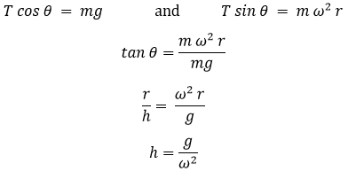
It is assumed that the sleeve is frictionless, the weight of links/ arms is negligible. Now the ball is in equilibrium under the action of the following force
- Centrifugal force acting on the balls, Fc = m ω2 r
- The weight of balls, w = mg
- Tension in the upper arms, T
OR
Take moment of these forces about O.
For equilibrium
Sleeve lift equal to 2 (h2 – h1)
h1 sleeve position at speed N1
h2 sleeve position at speed N2
- The height of the ball is independent of the mass of the ball, it only depends on the speed of the spindle.
- At higher speed, the sensitivity of watt governor will decrease.


